
Technical Parameters
| Technical parameter | Parameter value |
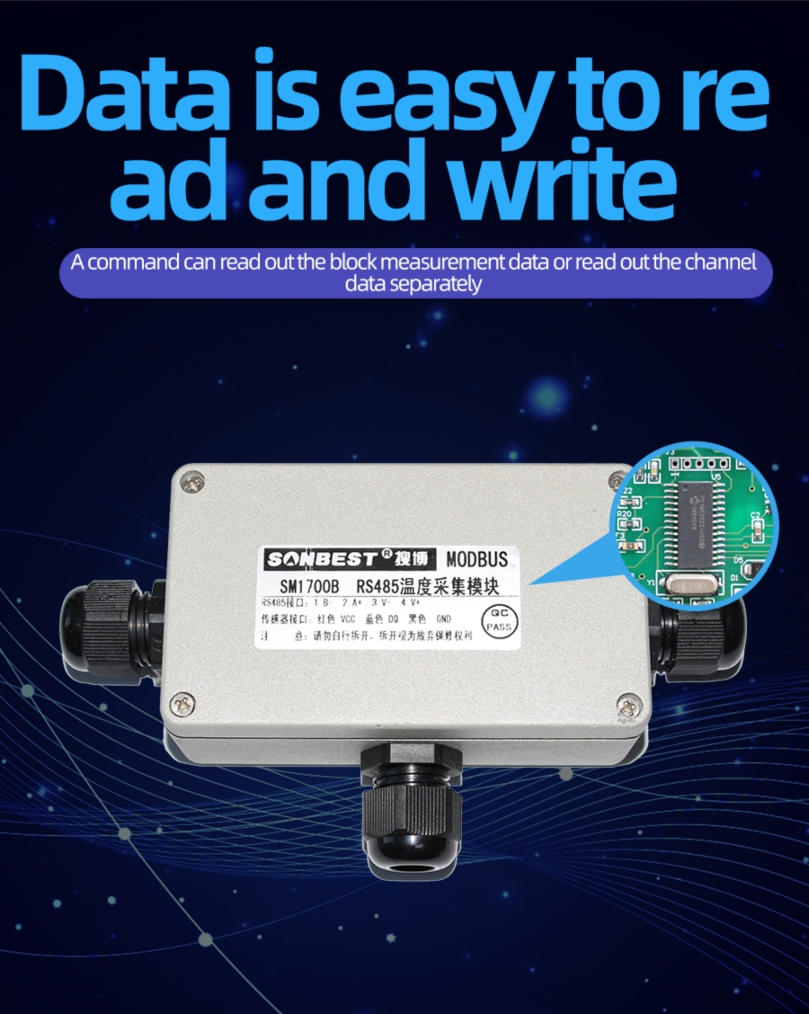
| Brand | SONBEST |
| Temperature measuring range | -30℃~85℃ |
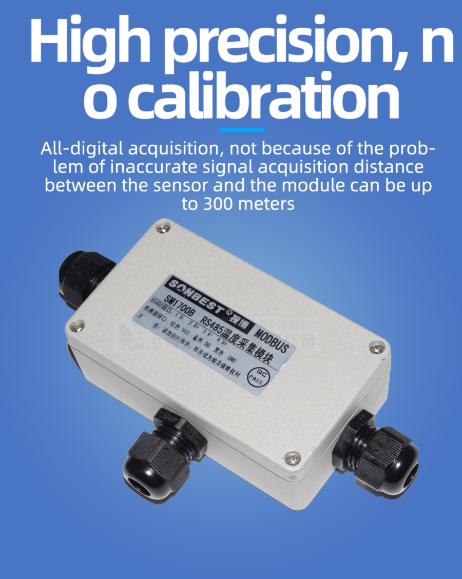
| Temperature measuring accuracy | ±0.5℃ @25℃ |
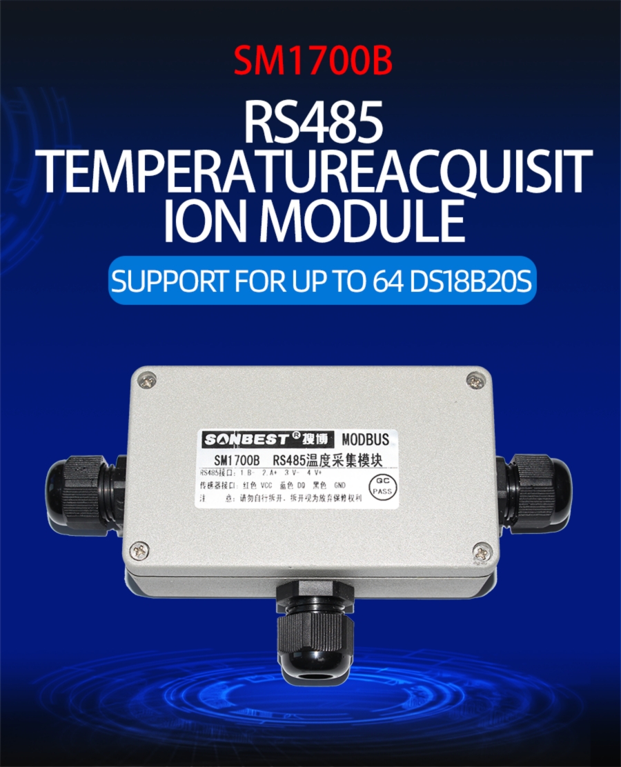
| Support sensors | 64 |
| Channels | 64 |
| Max Sensors of channel | 1 |
| Support sensor | sensor of DS18B20 |
| Communication Interface | RS485 |
| Default baud rate | 9600 8 n 1 |
| Power | DC9~24V 1A |
| Running temperature | -30~85℃ |
| Working humidity | 5%RH~90%RH |
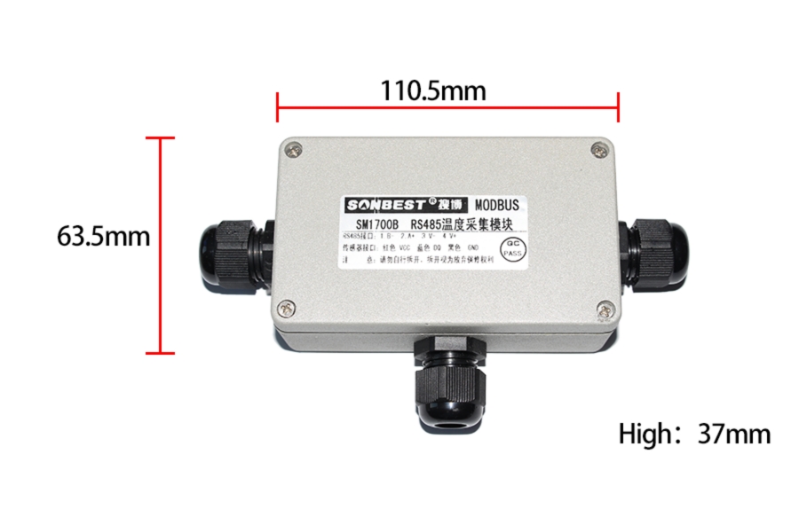
Product Size

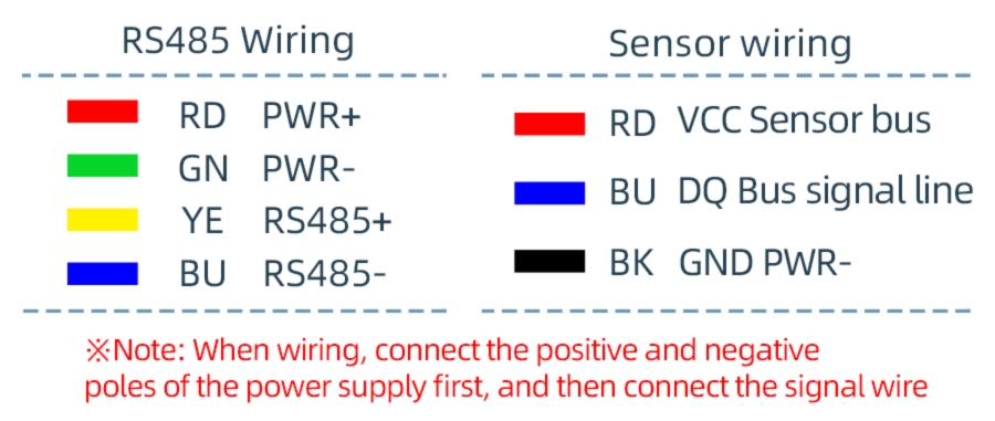
Wiring instructions
Why choose this product?

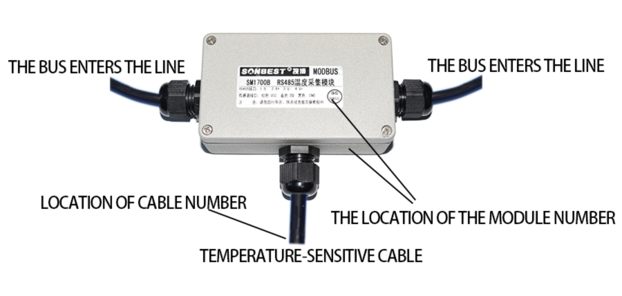
How to use?
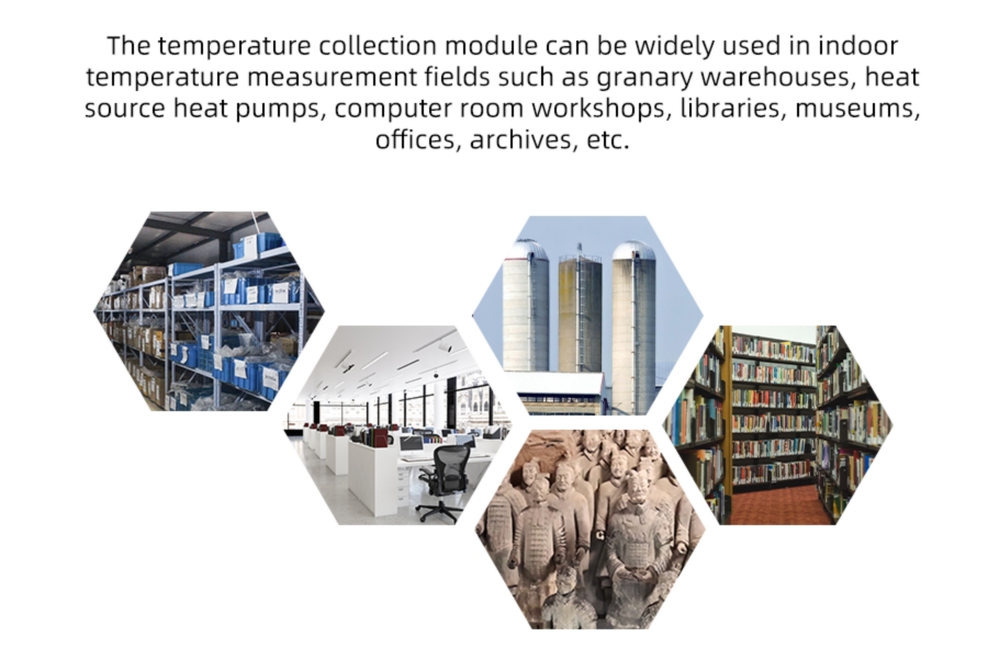
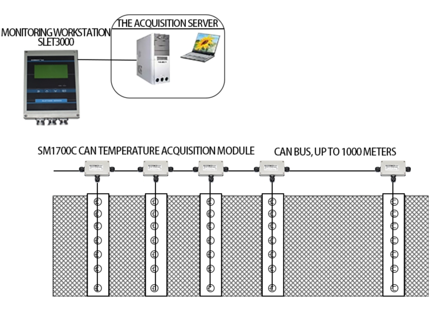
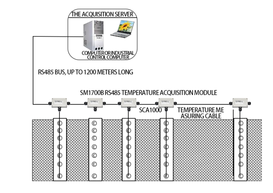
Application solution
Product List
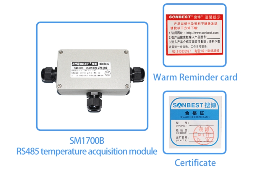
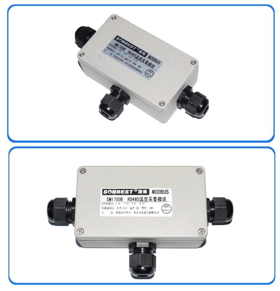
Pictures
Communication Protocol
The product uses RS485 MODBUS-RTU standard protocol format, all operation or reply commands are hexadecimal data. The default device address is 1 when the device leaves the factory, and the module or NON-Recorder default baud rate is 9600,8,n,1 ,but data recorder default baud rate is 115200 .1. Read data (function code 0x03)
The query frame (hexadecimal) is used to query the data of each measuring point or channel. For the multi-channel DS18B20 temperature module, since each channel supports a large number of points, each query frame There is also a limit on the length of reply bytes, so the device is designed to query data by channel. The device is divided into 64 channels, each channel supports a maximum of 1 measuring points, sending example: query 1 #All measuring point data on channel 1 of the device, the host computer sends the command: 01 03 01 01 00 01 D4 36 .
| Address | Function Code | Start Address | Data Length | Check Code |
| 01 | 03 | 01 01 | 00 01 | D4 36 |
| Address | Function Code | Length | 测点1 | Check Code |
| 01 | 03 | 02 | 00 79 | 79 A6 |
2. Common data address table
In order to query the data of the standby channel, the node address can be addressed. The device queries data by There are 10 channels, and only 10 query commands are used to find out all the data of the device. The relationship between the starting address of each channel and the 4xxxx address in the configuration software is shown in the table, and its basic calculation method is: n* 256+02, where n is the channel number. For example, the register at position 1 of channel 1 is 40258.
| Configuration Address | Register Address | Register Description | Data Type | Value Range |
| 40258 | 01 01 | 1CH 1#PTemperature | Read Only | 0~65535 |
| 40259 | 01 02 | 1CH 2#PTemperature | Read Only | 0~65535 |
| ...... | ..... | (1 Omission of mid-channel measurement points) | ... | ... |
| 40259 | 01 01 | 1CH 1#PTemperature | Read Only | 0~65535 |
| 40514 | 02 01 | 2CH 1#PTemperature | Read Only | 0~65535 |
| 40515 | 02 02 | 2CH 2#PTemperature | Read Only | 0~65535 |
| ...... | ..... | (2 Omission of mid-channel measurement points) | ... | ... |
| 40515 | 02 01 | 2CH 1#PTemperature | Read Only | 0~65535 |
| ---- | ---- | Middle channel omitted ) | ---- | ---- |
| 416386 | 03 01 | 64CH 1#PTemperature | Read Only | 0~65535 |
| 416387 | 03 02 | 64CH 2#PTemperature | Read Only | 0~65535 |
| ...... | ..... | (64 Omission of mid-channel measurement points) | ... | ... |
| 416387 | 03 01 | 64CH 1#PTemperature | Read Only | 0~65535 |
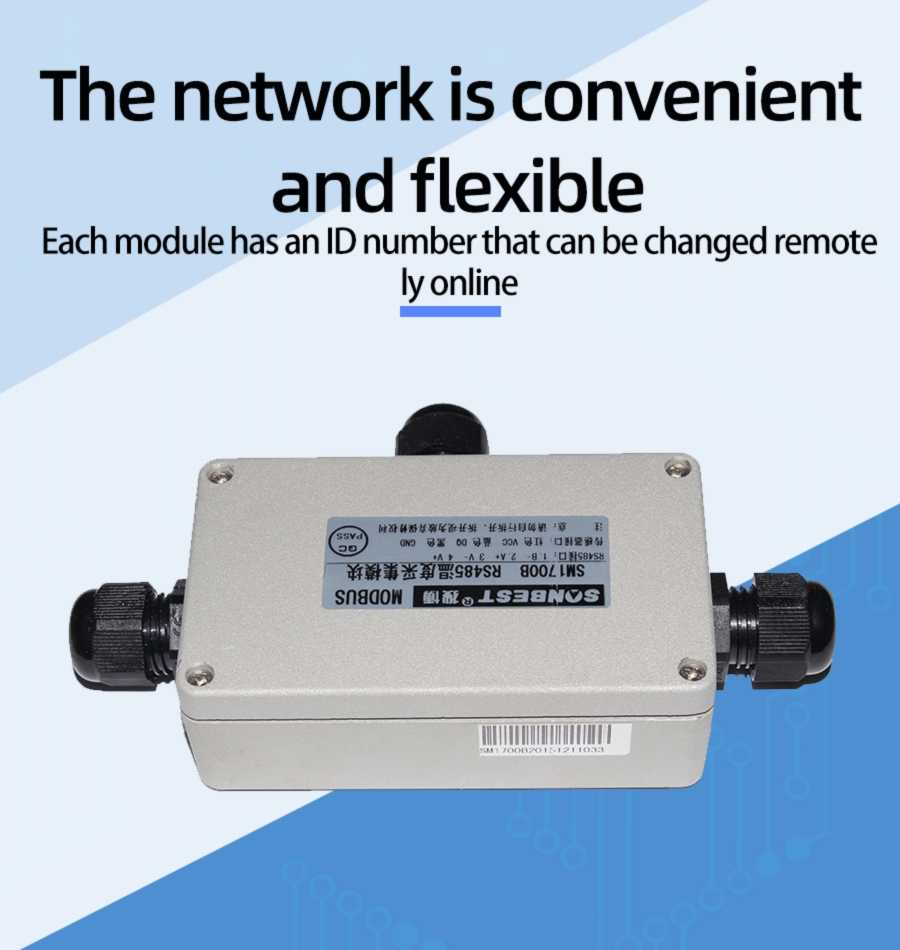
(1) Modify device address
The device sets the device address and baud rate through the dial switch on the left side of the product. In the application, when multiple machines are required to be networked, the device addresses in the network cannot be the same, so the user needs to change the device Address, the address range that can be changed by the device is 1-63. The address of the device can be changed by DIP switch S1. Dial the DIP switch to [ON] to indicate 1, and the 1-6 segments of the DIP switch S1 are related to the address. The relevant system is shown in the following table:
| Segment 6 | Segment 5 | Segment 4 | Segment 3 | Segment 2 | Segment 1 | Address value |
| 0 | 0 | 0 | 0 | 0 | 0 | 1 |
| 0 | 0 | 0 | 0 | 0 | 0 | 2 |
| 0 | 0 | 0 | 0 | 0 | 0 | 3 |
| 0 | 0 | 0 | 0 | 0 | 0 | 4 |
| ... | ... | ... | ... | ... | ... | n |
| 1 | 1 | 1 | 1 | 1 | 1 | 63 |
The baud rate setting is realized by the first 3 segments of the DIP switch S2. The fourth segment of S2 is not enabled and can be pulled to the 0 position. As shown in the figure on the right, the DIP switch is dialed to [ON] means 1, and pulling it to the side of the number means 0, the meaning is as follows.
| Segment 3 | Segment 2 | Segment 1 | Baud Rate |
| 0 | 0 | 0 | 9600 |
| 0 | 0 | 1 | 9600 |
| 0 | 1 | 0 | 4800 |